IoT Connections
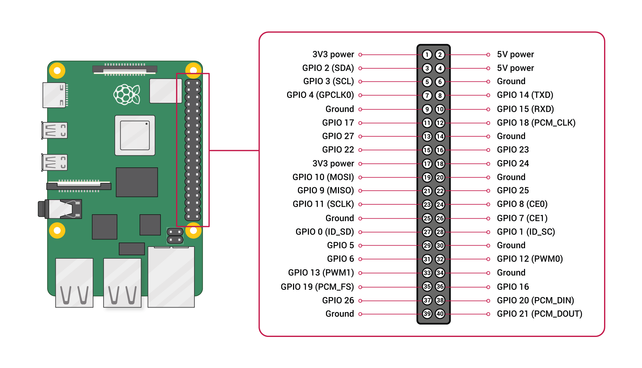
Refer Raspberry Pi pinout diagram

Assignment 2 - LEDs and Buzzer
Single LED
| Device |
Positive terminal |
Negative terminal (Ground/GND) |
Signal/Output |
| LED |
GPIO 16 (PIN 36) |
GROUND (PIN 34) |
N/A |
Two LEDs
| Device |
Positive terminal |
Negative terminal (Ground/GND) |
Signal/Output |
| LED 1 |
GPIO 16 (PIN 36) |
GROUND (PIN 34) |
N/A |
| LED 2 |
GPIO 26 (PIN 37) |
GROUND (PIN 39) |
N/A |
Buzzer with one LED
| Device |
Positive terminal |
Negative terminal (Ground/GND) |
Signal/Output |
| Buzzer |
GPIO 16 (PIN 36) |
GROUND (PIN 34) |
N/A |
| LED |
GPIO 26 (PIN 37) |
GROUND (PIN 39) |
N/A |
Assignment 3 - IR Sensor
| Device |
Positive terminal |
Negative terminal (Ground/GND) |
Signal/Output |
| IR Sensor |
5V power (PIN 2) |
GROUND (PIN 34) |
GPIO 16 (PIN 36) |
| LED |
GPIO 26 (PIN 37) |
GROUND (PIN 39) |
N/A |
Assignment 4 - DHT11 (Temperature sensor)
| Device |
Positive terminal |
Negative terminal (Ground/GND) |
Signal/Output |
| DHT11 |
5V power (PIN 2) |
GROUND (PIN 34) |
GPIO 16 (PIN 36) |
Assignment 5 - Camera
| Device |
Positive terminal |
Negative terminal (Ground/GND) |
Signal/Output |
| Picamera |
N/A |
N/A |
CSI port |
Water level
| Device |
Positive terminal |
Negative terminal (Ground/GND) |
Signal/Output |
| Water sensor |
5V power (PIN 2) |
GROUND (PIN 34) |
GPIO 16 (PIN 36) |
| LED |
GPIO 26 (PIN 37) |
GROUND (PIN 39) |
N/A |
